4-axis linear system with 15,000 N
A complete redesign of an existing machine around the X1 controller - mechanical and electrical engineering from one team.
- Mechanical engineering
- Electronics
- FMEA risk analysis
- Prototyping
The problem
The customer wanted a machine with four independently driven linear axes: three with a maximum lifting force of 15,000 N each, the fourth a special axis with quite different requirements.
Some axes were to carry two force sensors each, to measure the compressive and tensile force actually applied, plus limit switches for precise homing.
Because the machine is also to be sold in the US in future, a decentralised 48 VDC motor control was required.
A predecessor machine was already in service - its hardware problems were not to come along.
Our approach
We started by analysing the predecessor's characteristics and hardware problems and ran a risk analysis, so that every specification was on record.
Development time was short, so we worked with an external design engineer provided by the customer. Responsibility for signing off the mechanical implementation, for the drive technology and for all electrical engineering tasks stayed with us.
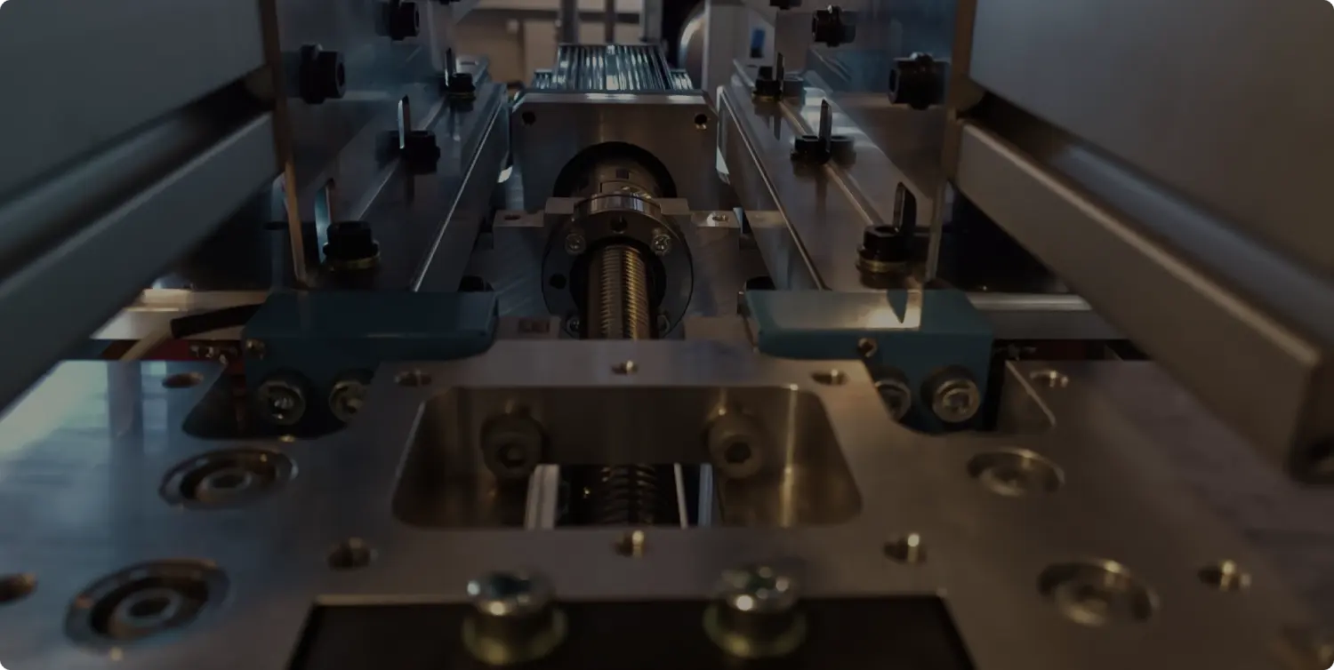
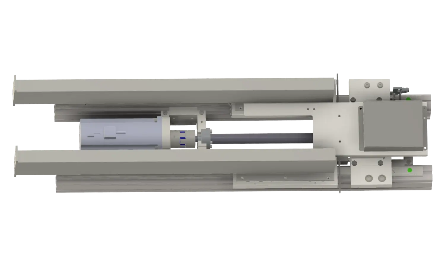
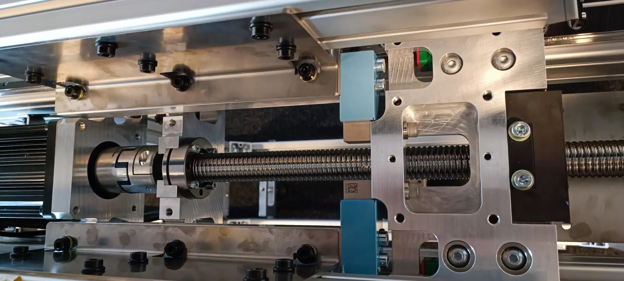
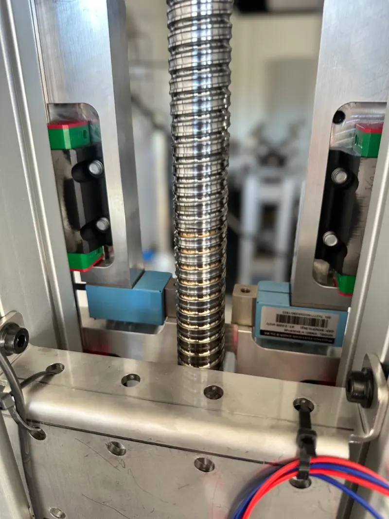
Because of the large forces, three axes were built with ball screws; the fourth, very short axis with small forces uses a trapezoidal screw with an automatic lubricator.
To bring production costs down, the mechanics had to absorb manufacturing tolerances - among other things, the carriages are floating-mounted.
We designed and produced several electronic boards per machine. Our X1 motor controller was adapted specifically, with predefined behaviours programmed straight into it.
Each axis got its own electrical box, so only CAN and power have to be routed to the axis. Peripherals such as the force sensors plug directly into that box; brake choppers protect the DC link from overvoltage during deceleration.
The subcomponents were tested early and independently. For the firmware and the control software we built a dev kit from one axis, limit switches and the sensors.
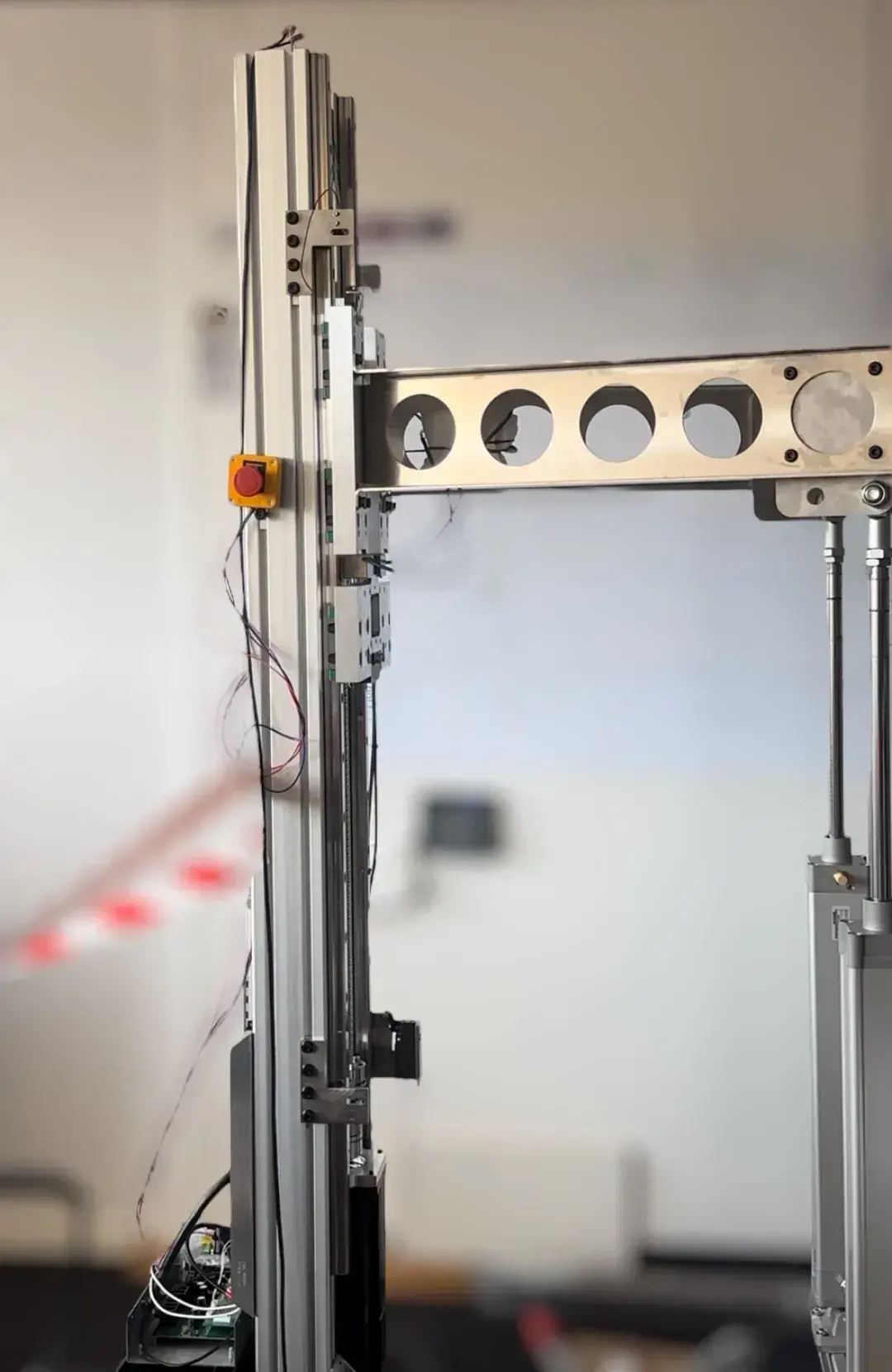
Before the first prototypes we built a functional model: pneumatic cylinders generated the opposing force for an endurance test over 100,000 cycles.
What came out of it
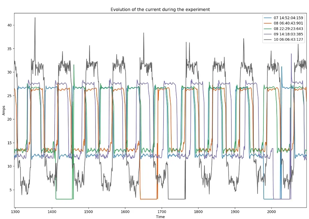
The endurance test ran at up to 300 measurement points per second - two force readings, position, speed and current.
At that data density, the smallest changes such as increasing friction became visible before they caused mechanical damage downstream. The test results fed straight back into the ongoing mechanical development.
The decentralised 48 VDC architecture keeps the machine ready for the planned distribution in the US.
Mechanical and electrical engineering came from one team - from the risk analysis through the boards to the firmware.
More projects
Got an idea or a project? Let's get started.
One hour, free of charge, by video or at our place in Zurich. We look at where the technical risks are, what can be shortened and what the next sensible step would be. No pitch, no slide deck. You leave with more clarity than you arrived with — even if we never work together.
Book an engineering sparringOr get in touch directly: info@akrodyn.com · +41 44 599 20 60
You speak straight to the engineer who will work on your project afterwards.